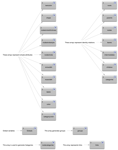
This is a low-level library (Ciper.Dgml.Schema.dll) that provides an object model on top of DGML documents; as such, it can be considered as a read/write abstraction layer on top of DGML documents. I have higher-level libraries and tools that provide more functionality based on this one (notably “Ciper.Dgml.dll”, “DGMLViewer” and “VisualDGML”).
There are four principal areas where you might need it:
1. Manipulate DGML outside Visual Studio
2. Even inside Visual Studio, use code instead of XML for processing DGML documents
3. Process DGML with a lower version of Visual Studio than “Ultimate” or “Premium” (e.g. “Visual Studio Professional” or even the “Express” versions)
4. Programmatically create, access and modify DGML documents without the need for Microsoft’s non-redistributable private DLLs (a.k.a. the “Progression API”)
Here are some of the things that you can do with it:
1. Create DGML documents
2. Modify and annotate DGML documents
3. Investigate/Manipulate a DGML document without having the proper Visual Studio version or even Visual Studio at all (maybe somebody with “Ultimate” sent it to you)
4. Use Linq over DGML
5. Write your own DGML tool with no dependencies on Visual Studio or its DLLs
6. Represent a DGML diagram using another graph visualization tool (such as “GraphViz”) (I have tools for that)
7. Translate DGML to SVG, maybe for consuming in your HTML (I have tools for that too)
var g = new DirectedGraph();
g.Nodes = new Nodes();
var n = new Node();
n.Id = “Ciper.Dgml.Schema”;
g.Nodes.Add(n);

The “Nodes” collection is optional, so it must be created explicitely.
Adding just nodes to a graph may not be great fun but it requires some knowlegde if you want to control its disposition:
var g = new DirectedGraph(true);
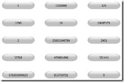
g.Nodes.Add(Enumerable.Range(1,15).Select(i => Math.Pow(i,i*2/3)));

Here nodes different sizes; to make them all the same size:
var g = new DirectedGraph(true);
g.Nodes.Add(Enumerable.Range(1,15).Select(i => new Node(Math.Pow(i,i*2/3)) { MinWidth = 100 }));
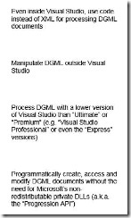
var reasons = new [] {
“Manipulate DGML outside Visual Studio”,
“Even inside Visual Studio, use code instead of XML for processing DGML documents”,
“Process DGML with a lower version of Visual Studio than “Ultimate” or “Premium” (e.g. “Visual Studio Professional” or even the “Express” versions)”,
“Programmatically create, access and modify DGML documents without the need for Microsoft’s non-redistributable private DLLs (a.k.a. the “Progression API”)”,
};
var g = new DirectedGraph(true);
g.Nodes.Add(reasons);

var reasons = new[] {
“Manipulate DGML outside Visual Studio”,
“Even inside Visual Studio, use code instead of XML for processing DGML documents”,
“Process DGML with a lower version of Visual Studio than “Ultimate” or “Premium” (e.g. “Visual Studio Professional” or even the “Express” versions)”,
“Programmatically create, access and modify DGML documents without the need for Microsoft’s non-redistributable private DLLs (a.k.a. the “Progression API”)”,
};
var g = new DirectedGraph(true) { GraphDirection = “TopToBottom” };
g.Nodes.Add(reasons.Select(s => new Node(s)
{ MaxWidth = 150, MinWidth = 150, Background = “Transparent”, Foreground = “Black”, Stroke = “Transparent”, FontFamily = “Arial” }));
Chaging a Node’s Shape
var g = new DirectedGraph();
g.Nodes = new Nodes();
g.Nodes.Add(new Node { Id=”Ciper.Dgml.Schema”, NodeRadius=0 });
g.Nodes.Add(new Node { Id=”Ciper.Dgml”, NodeRadius=4 });
g.Nodes.Add(new Node { Id=”DGMLViewer”, NodeRadius=50 });

Here, “Ciper.Dgml.Schema” is the low-level library, “Ciper.Dgml” is the proper DGML library and “DGMLViewer” is the viewer that lets you view DGML documents outside Visual Studio.
Although “Node” has a “Shape” property, it is only used to suppress the usage of any shape and thus accepts a single value: “None”.
var g = new DirectedGraph();
g.Nodes = new Nodes();
g.Nodes.Add(new Node { Id=”DGMLViewer” });
g.Nodes.Add(new Node { Id=”Ciper.Dgml.Schema”, Shape = “None” });

This is especially useful when icons are used in nodes.
Adding Icons to Nodes
var g = new DirectedGraph();
g.Nodes = new Nodes();
g.Nodes.Add(new Node { Id=”1″, Label = “File”, Icon = “File” });
g.Nodes.Add(new Node { Id=”2″, Label = “File”, Icon = “File”, Shape = “None” });

I don’t know why this works but “File” seems to be an intrinsic icon (not like the stock icons that come with the Progression DLLs). And I don’t know what others are there; I bumped into this one by luck.
Here are some icons:
var g = new DirectedGraph();
g.Nodes = new Nodes();
var icons = new[] { “DLL”, “Document”, “Layer”, “Library”, “Model” };
foreach (var icon in icons)
{
g.Nodes.Add(new Node
{
Id = icon,
Icon = string.Format(@”C:\Ceyhun\PrivateProjects\Ciper.Dgml.Schema\Icons\{0}_32x32.png”, icon),
Shape = “None”, VerticalAlignment = “Bottom”, HorizontalAlignment = “Center”
});
}

var g = new DirectedGraph();
g.Nodes = new Nodes();
var components = new[] {
new { Id = “Ciper.Dgml.Schema”, Icon = “DLL” },
new { Id = “DGML”, Icon = “Document” },
new { Id = “Ciper.Dgml.Svg”, Icon = “Layer” },
new { Id = “Ciper.Dgml”, Icon = “Library” },
new { Id = “DGMLViewer”, Icon = “Model” },
};
foreach (var component in components)
{
g.Nodes.Add(new Node
{
Id = component.Id,
Icon = string.Format(@”C:\Ceyhun\PrivateProjects\Ciper.Dgml.Schema\Icons\{0}_32x32.png”, component.Icon),
Shape = “None”, VerticalAlignment = “Bottom”, HorizontalAlignment = “Center”
});
}

Here, DGML is the document, Ciper.Dgml.Schema is the low-level DLL, Ciper.Dgml is the library, Ciper.Dgml.Svg is the layer that converts DGML to SVG and DGMLViewer is the tool that visualizes DGML without any need for Visual Studio.
There are some stock icons:
var g = new DirectedGraph(true);
g.Nodes.Add(new Node(“Globe”) { Icon = Icons.globe });
g.Nodes.Add(new Node(“Printer”) { Icon = Icons.printer });
g.Nodes.Add(new Node(“Monitor”) { Icon = Icons.monitor });
g.Nodes.Add(new Node(“Users”) { Icon = Icons.users });

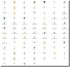
Here is all of them:
var g = new DirectedGraph(true);
var icons =
from name in Icons.ProgressionIconNames
select new Node(name)
{
Icon = Icons.ProgressionIcons[name],
HorizontalAlignment = “Center”, MinWidth = 150, Shape = “None”
};
g.Nodes.Add(icons);
Chaging a Node’s Style
Although “Node” has a style property, it has nothing to do with DGML “Styles”; it accepts only one value: “Plain”; this is in case you don’t like or prefer the “Glass” look.
var g = new DirectedGraph();
g.Nodes = new Nodes();
g.Nodes.Add(new Node { Id=”1″, Background = “Olive” });
g.Nodes.Add(new Node { Id=”2″, Background = “Olive”, Style = “Plain” });

1. Show all files in a folder
2. Show all types in an assembly
var g = new DirectedGraph();
g.Nodes = new Nodes();
g.Nodes.Add(new Node { Id = “Ciper.Dgml” });
g.Nodes.Add(new Node { Id = “Ciper.Dgml.Schema” });
g.Links = new Links();
g.Links.Add(new Link { Source = “Ciper.Dgml”, Target = “Ciper.Dgml.Schema” });
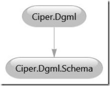
The “Links” collection is optional, so it must be created explicitely.
References between nodes and links are resolved via nodes’ Id’s instead of node instances; this weakly-typed approach is error-prone because the existence of nodes involved is not checked; the graph will be viewed and used correctly in Visual Studio but probably not outside it (i.e. in some other consuming program, such as my “DGMLViewer” and “VisualDGML” tools). So a better approach is to use specific instances of nodes when creating links:
var g = new DirectedGraph();
g.Nodes = new Nodes();
var n1 = g.Nodes.Add(new Node { Id = ” Ciper.Dgml” });
var n2 = g.Nodes.Add(new Node { Id = ” Ciper.Dgml.Schema” });
g.Links = new Links();
g.Links.Add(new Link(n1, n2));
As the nodes do not have to be added explicitely, even the following shortcut can be taken (in Visual Studio the nodes will be created automatically when a link is created):
var g = new DirectedGraph();
g.Links = new Links();
g.Links.Add(new Link { Source = ” Ciper.Dgml”, Target = ” Ciper.Dgml.Schema” });
However, as the nodes will not exist in the resulting DGML file, consumer applications other than Visual Studio will probably fail to process it.
var g = new DirectedGraph();
g.Nodes = new Nodes();
g.Nodes.Add(new Node { Id = “Ciper.Dgml” });
g.Nodes.Add(new Node { Id = “Ciper.Dgml.Schema” });
g.Links = new Links();
g.Links.Add(new Link { Source = “Ciper.Dgml”, Target = “Ciper.Dgml.Schema”, Label = “depends on” });
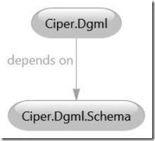
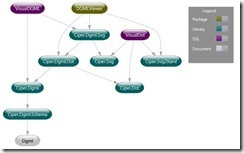
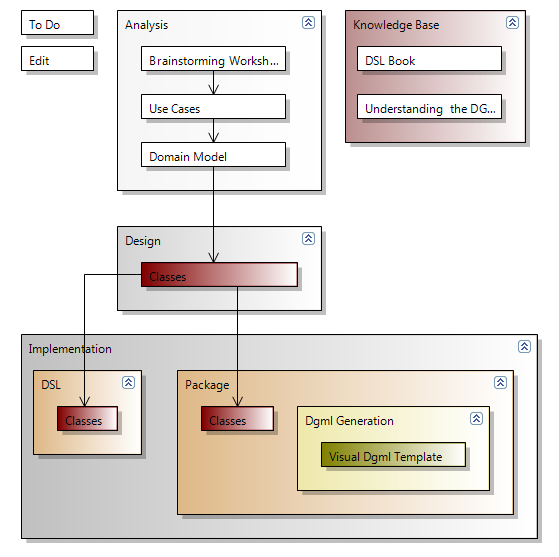
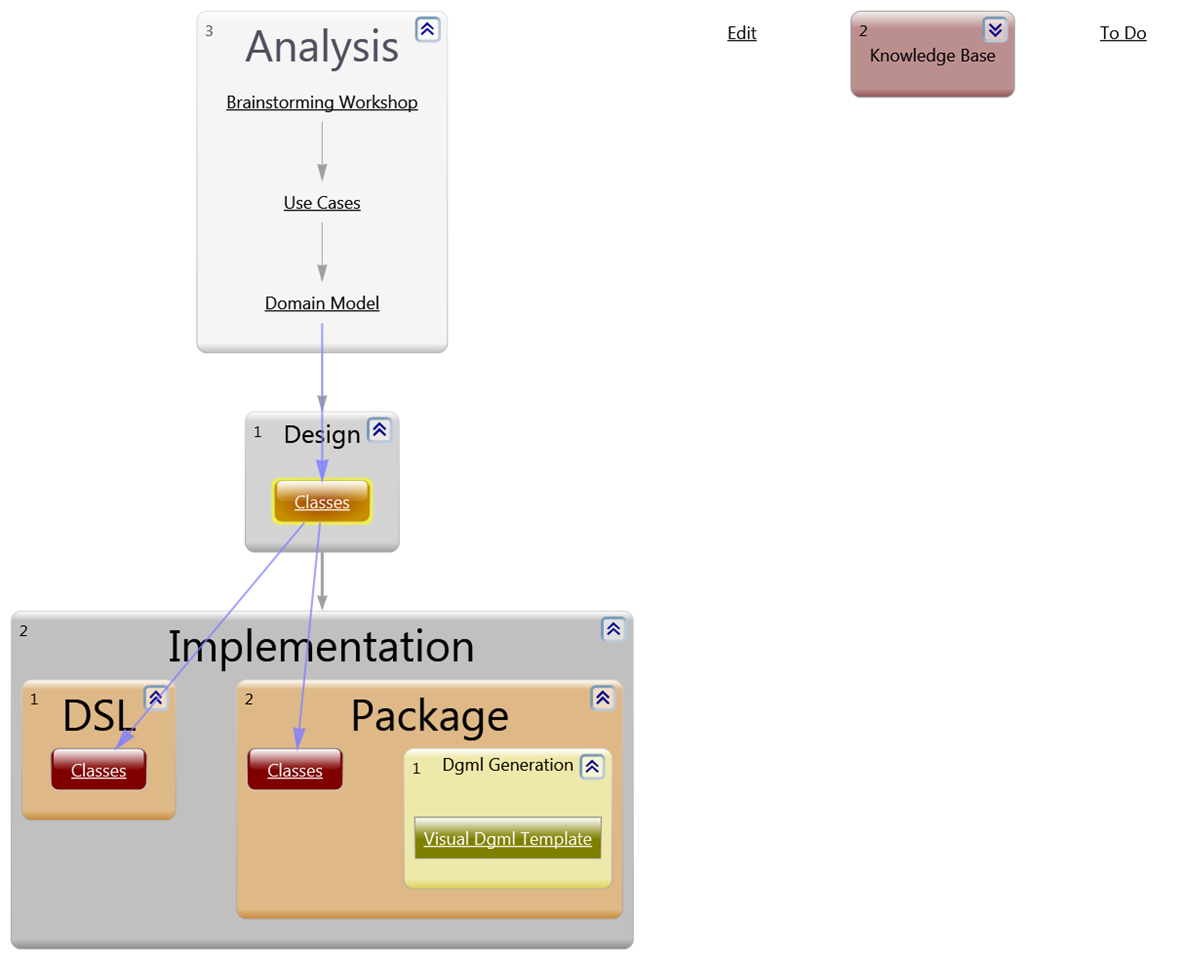
Here is the structure of the projects in the DGML panoply:
var g = new DirectedGraph();
g.Nodes = new Nodes();
g.Nodes.Add(new Node(“VisualDGML”)
{ Icon = @”C:\Ceyhun\PrivateProjects\Ciper.Dgml.Schema\Icons\DSL_32x32.png”,
Foreground = “#FF000080” });
g.Nodes.Add(new Node(“DGMLViewer”)
{ Icon = @”C:\Ceyhun\PrivateProjects\Ciper.Dgml.Schema\Icons\Package_32x32.png”,
Foreground = “#FF000080” });
g.Nodes.Add(new Node(“Ciper.Dgml.Svg”)
{ Icon = @”C:\Ceyhun\PrivateProjects\Ciper.Dgml.Schema\Icons\Library_32x32.png” });
g.Nodes.Add(new Node(“Ciper.Dgml.Dot”)
{ Icon = @”C:\Ceyhun\PrivateProjects\Ciper.Dgml.Schema\Icons\Library_32x32.png” });
g.Nodes.Add(new Node(“Ciper.Dgml”)
{ Icon = @”C:\Ceyhun\PrivateProjects\Ciper.Dgml.Schema\Icons\Library_32x32.png” });
g.Nodes.Add(new Node(“Ciper.Dgml.Schema”)
{ Icon = @”C:\Ceyhun\PrivateProjects\Ciper.Dgml.Schema\Icons\Library_32x32.png”,
Foreground = “#FF800000” });
g.Nodes.Add(new Node(“Dgml Document”)
{ Icon = @”C:\Ceyhun\PrivateProjects\Ciper.Dgml.Schema\Icons\Document_32x32.png” });
g.Links = new Links();
g.Links.Add(new Link { Source = “Ciper.Dgml.Schema”, Target = “Dgml Document”, Label = “serializes” });
g.Links.Add(new Link { Source = “Ciper.Dgml”, Target = “Ciper.Dgml.Schema”, Label = “abstracts” });
g.Links.Add(new Link { Source = “Ciper.Dgml.Dot”, Target = “Ciper.Dgml” });
g.Links.Add(new Link { Source = “Ciper.Dgml.Svg”, Target = “Ciper.Dgml.Dot” });
g.Links.Add(new Link { Source = “VisualDGML”, Target = “Ciper.Dgml.Svg” });
g.Links.Add(new Link { Source = “VisualDGML”, Target = “Ciper.Dgml” });
g.Links.Add(new Link { Source = “DGMLViewer”, Target = “Ciper.Dgml.Svg” });
g.Links.Add(new Link { Source = “DGMLViewer”, Target = “Ciper.Dgml.Dot” });
foreach (var node in g.Query.Descendants<Node>())
{
node.HorizontalAlignment = “Center”;
node.VerticalAlignment = “Bottom”;
node.Shape = “None”;
}

1. Display a table
2. Show the Paris Metro
3. Show neighboring countries in Europe
Display a table
var software = new[] {
new Node(“DGMLViewer”, “Package”),
new Node(“VisualDGML”, “DSL”),
new Node(“VisualDot”, “DSL”),
new Node(“Ciper.Dgml”, “Library”),
new Node(“Ciper.Dgml.Svg”, “Library”),
new Node(“Ciper.Dgml.Dot”, “Library”),
new Node(“Ciper.Dgml.Schema”, “Library”),
new Node(“Ciper.Dot”, “Library”),
new Node(“Ciper.Svg”, “Library”),
new Node(“Ciper.Svg2Xaml”, “Library”),
new Node(“Dgml”, “Document”),
};
var g = new DirectedGraph(true) { GraphDirection = “LeftToRight” };
var dummy = g.Nodes.Add(new Node(” “) { Shape = “None” });
foreach (var s in software)
{
var catNode = g.Nodes.Add(new Node(s.Id+s.Category1) { Label = s.Category1 });
g.Links.AddPath(s, catNode, dummy);
}
g.Styles.Add(new Style
{
TargetType = “Node”,
Setters =
{
new Setter(“MinWidth”, “100”),
new Setter(“MaxWidth”, “100”),
new Setter(“NodeRadius”, “0”),
new Setter(“Background”, “Transparent”),
new Setter(“FontFamily”, “Gill Sans MT”),
new Setter(“Stroke”, “Transparent”),
new Setter(“Foreground”, “Black”),
}
});
g.Styles.Add(“Link”, “Stroke”, “Transparent”);
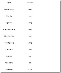
var g = new DirectedGraph();
g.Nodes = new Nodes();
g.Nodes.Add(new Node { Id = “France”, Group = “Expanded” });
g.Links = new Links();
g.Links.Add(new Link { Source = “Country”, Target = “France” });
g.Links.Add(new Link { Source = “Town”, Target = “Paris” });
g.Links.Add(new Link { Source = “France”, Target = “Paris”, Category1 = “Contains” });
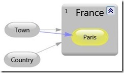
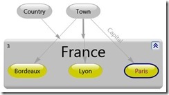
The “Group” property on “Node” does not have to be specified; if it is not, the node will look like a normal “Node” instead of a “Group”; however it can be shown as a group by choosing the “Show as Group” option in the DGML Viewer popup menu; what characterizes a “Node” as a group is actually the “Contains” value of the “Category1” property on the “Link” that has the node as source.
var g = new DirectedGraph();
g.Links = new Links();
g.Links.Add(new Link { Source = “Country”, Target = “France” });
g.Links.Add(new Link { Source = “Town”, Target = “Paris” });
g.Links.Add(new Link { Source = “France”, Target = “Paris”, Category1 = “Contains” });
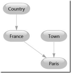
var g = new DirectedGraph();
g.Nodes = new Nodes();
g.Nodes.Add(new Node { Id = “France”, Group = “Expanded” });
g.Links = new Links();
g.Links.Add(new Link { Source = “Country”, Target = “France” });
g.Links.Add(new Link { Source = “Town”, Target = “Paris”, Label = “Capital” });
g.Links.Add(new Link { Source = “Town”, Target = “Lyon” });
g.Links.Add(new Link { Source = “France”, Target = “Paris”, Category1 = “Contains” });
g.Links.Add(new Link { Source = “France”, Target = “Lyon”, Category1 = “Contains” });
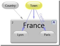
var software = new[] {
new { Id = 1000, Name = “DGMLViewer”, Kind = “Package”, Refs = new[] { 1101, 1102 } },
new { Id = 1010, Name = “VisualDGML”, Kind = “DSL”, Refs = new[] { 1100, 1101 } },
new { Id = 1011, Name = “VisualDot”, Kind = “DSL”, Refs = new[] { 1100 } },
new { Id = 1100, Name = “Ciper.Dgml”, Kind = “Library”, Refs = new[] { 1103 } },
new { Id = 1101, Name = “Ciper.Dgml.Svg”, Kind = “Library”, Refs = new[] { 1102 } },
new { Id = 1102, Name = “Ciper.Dgml.Dot”, Kind = “Library”, Refs = new[] { 1100 } },
new { Id = 1103, Name = “Ciper.Dgml.Schema”, Kind = “Library”, Refs = new[] { 1200 } },
new { Id = 1200, Name = “Dgml”, Kind = “Document”, Refs = new int[0] },
};
var iconPath = @”C:\Ceyhun\PrivateProjects\Ciper.Dgml.Schema\Icons”;
var g = new DirectedGraph { Background = “#FF004040” };
g.Nodes = new Nodes();
g.Nodes.Add(new Node { Id = “Packages”, Group = “Expanded”, Background=”#FF006060″ });
g.Nodes.Add(new Node { Id = “DSLs”, Group = “Expanded”, Background=”#FF606000″ });
g.Nodes.Add(new Node { Id = “Libraries”, Group = “Expanded”, Background=”#FF406060″ });
foreach (var s in software)
g.Nodes.Add(new Node(s.Id.ToString())
{
Label = s.Name, Foreground=”White”,
Icon = string.Format(@”{0}\{1}_32x32.png”, iconPath, s.Kind),
Shape = “None”, HorizontalAlignment = “Center”, VerticalAlignment = “Bottom”
});
g.Links = new Links();
var groups = from s in software
where s.Kind != “Document”
group s by s.Kind into sg
let category = Regex.Replace(sg.Key, “y$”, “ie”)+”s”
from soft in sg
let link = g.Links.Add(category, soft.Id.ToString(), true)
select link;
groups.ToList(); // Execute the query
var links = from s in software
from r in s.Refs
let link = g.Links.Add(s.Id.ToString(), r.ToString())
select link;
links.ToList(); // Execute the query
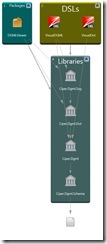
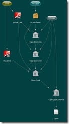
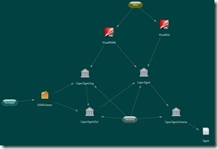
![clip_image048[1] clip_image048[1]](https://ceyhunciper.files.wordpress.com/2011/04/clip_image0481_thumb.jpg?w=244&h=244)
1. Show all types, methods and properties in the “System” namespace
var g = new DirectedGraph();
g.Nodes = new Nodes();
g.Nodes.Add(new Node { Id = “France”, Group = “Expanded” });
g.Nodes.Add(new Node { Id = “Paris”, Category1 = “Fashion” });
g.Nodes.Add(new Node { Id = “Lyon”, Category1 = “Gastronomy” });
g.Nodes.Add(new Node { Id = “Bordeaux”, Category1 = “Gastronomy” });
g.Links = new Links();
g.Links.Add(new Link { Source = “Town”, Target = “Paris”, Label = “Capital” });
g.Links.Add(new Link { Source = “Country”, Target = “France” });
g.Links.Add(new Link { Source = “Town”, Target = “Lyon” });
g.Links.Add(new Link { Source = “Town”, Target = “Bordeaux” });
g.Links.Add(new Link { Source = “France”, Target = “Paris”, Category1 = “Contains” });
g.Links.Add(new Link { Source = “France”, Target = “Lyon”, Category1 = “Contains” });
g.Links.Add(new Link { Source = “France”, Target = “Bordeaux”, Category1 = “Contains” });
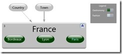
![clip_image050[1] clip_image050[1]](https://ceyhunciper.files.wordpress.com/2011/04/clip_image0501_thumb.jpg?w=244&h=109)
This approach is valid only if you are adding a single category.
var g = new DirectedGraph();
g.Nodes = new Nodes();
g.Nodes.Add(new Node(“France”, GroupType.Expanded));
g.Nodes.Add(new Node(“US”, GroupType.Expanded));
g.Nodes.Add(new Node(“Paris”, “Fashion”));
g.Nodes.Add(new Node(“Lyon”, “Gastronomy”));
g.Nodes.Add(new Node(“Bordeaux”, “Gastronomy”));
g.Nodes.Add(new Node(“New York”, “Finance”));
g.Links = new Links();
g.Links.Add(new Link(“Town”, “Paris”) { Label = “Capital” });
g.Links.Add(new Link(“Town”, “Washington D.C.”) { Label = “Capital” });
g.Links.AddPairs(“Country”, “France”, “Country”, “US”, “Town”, “Lyon”, “Town”, “Bordeaux”, “Town”, “New York”);
g.Links.AddContainers(“France”, “Paris”, “Lyon”, “Bordeaux”);
g.Links.AddContainers(“US”, “Washington D.C.”, “New York”);

var software = new[] {
new { Id = 1000, Name = “DGMLViewer”, Kind = “Package”, Refs = new[] { 1101, 1102, 1106 } },
new { Id = 1010, Name = “VisualDGML”, Kind = “DSL”, Refs = new[] { 1100, 1101 } },
new { Id = 1011, Name = “VisualDot”, Kind = “DSL”, Refs = new[] { 1104, 1105, 1106 } },
new { Id = 1100, Name = “Ciper.Dgml”, Kind = “Library”, Refs = new[] { 1103 } },
new { Id = 1101, Name = “Ciper.Dgml.Svg”, Kind = “Library”, Refs = new[] { 1102, 1105 } },
new { Id = 1102, Name = “Ciper.Dgml.Dot”, Kind = “Library”, Refs = new[] { 1100, 1104 } },
new { Id = 1103, Name = “Ciper.Dgml.Schema”, Kind = “Library”, Refs = new[] { 1200 } },
new { Id = 1104, Name = “Ciper.Dot”, Kind = “Library”, Refs = new int[0] },
new { Id = 1105, Name = “Ciper.Svg”, Kind = “Library”, Refs = new int[0] },
new { Id = 1106, Name = “Ciper.Svg2Xaml”, Kind = “Library”, Refs = new int[0] },
new { Id = 1200, Name = “Dgml”, Kind = “Document”, Refs = new int[0] },
};
var g = new DirectedGraph { Nodes = new Nodes(), Links = new Links() };
var links = from s in software
let node = g.Nodes.Add(new Node(s.Id, s.Kind) { Label=s.Name })
from r in s.Refs
select g.Links.Add(s.Id, r);
links.ToList(); // Execute the query
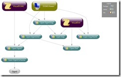
var g = new DirectedGraph();
g.Nodes = new Nodes();
g.Nodes.Add(new Node { Id = “France”, Group = “Expanded” });
var paris = new Node { Id = “Paris”, Category1 = “Fashion” };
paris.Category.Add(new Node.CategoryLocalType { Ref = “Gastronomy” });
g.Nodes.Add(paris);
g.Nodes.Add(new Node { Id = “Lyon”, Category1 = “Gastronomy” });
g.Nodes.Add(new Node { Id = “Bordeaux”, Category1 = “Gastronomy” });
g.Links = new Links();
g.Links.Add(new Link { Source = “Town”, Target = “Paris”, Label = “Capital” });
g.Links.Add(new Link { Source = “Country”, Target = “France” });
g.Links.Add(new Link { Source = “Town”, Target = “Lyon” });
g.Links.Add(new Link { Source = “Town”, Target = “Bordeaux” });
g.Links.Add(new Link { Source = “France”, Target = “Paris”, Category1 = “Contains” });
g.Links.Add(new Link { Source = “France”, Target = “Lyon”, Category1 = “Contains” });
g.Links.Add(new Link { Source = “France”, Target = “Bordeaux”, Category1 = “Contains” });
var g = new DirectedGraph();
g.Nodes = new Nodes();
g.Nodes.Add(new Node { Id = “France”, Group = “Expanded” });
var paris = new Node { Id = “Paris”, Category1 = “Fashion” };
paris.Category.Add(new Node.CategoryLocalType { Ref = “Gastronomy” });
paris.Category.Add(new Node.CategoryLocalType { Ref = “Capital” });
g.Nodes.Add(paris);
g.Nodes.Add(new Node { Id = “Lyon”, Category1 = “Gastronomy” });
g.Nodes.Add(new Node { Id = “Bordeaux”, Category1 = “Gastronomy” });
g.Links = new Links();
g.Links.Add(new Link { Source = “Town”, Target = “Paris”, Label = “Capital” });
g.Links.Add(new Link { Source = “Country”, Target = “France” });
g.Links.Add(new Link { Source = “Town”, Target = “Lyon” });
g.Links.Add(new Link { Source = “Town”, Target = “Bordeaux” });
g.Links.Add(new Link { Source = “France”, Target = “Paris”, Category1 = “Contains” });
g.Links.Add(new Link { Source = “France”, Target = “Lyon”, Category1 = “Contains” });
g.Links.Add(new Link { Source = “France”, Target = “Bordeaux”, Category1 = “Contains” });
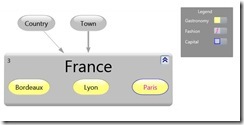
Note that the styles of different towns are set manually here; later we will see how to apply these styles programmatically.
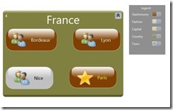
But why make “Country” and “Town” nodes when we can assign categories to corresponding nodes?
var g = new DirectedGraph();
g.Nodes = new Nodes();
g.Nodes.Add(new Node { Id = “France”, Group = “Expanded”, Category1 = “Country” });
g.Nodes.Add(new Node(“Paris”)).AddCategories(“Gastronomy”, “Capital”, “Fashion”, “Town”);
g.Nodes.Add(new Node(“Lyon”)).AddCategories(“Gastronomy”, “Town”);
g.Nodes.Add(new Node(“Bordeaux”)).AddCategories(“Gastronomy”, “Town”);
g.Nodes.Add(new Node(“Nice”)).AddCategories(“Town”);
g.Links = new Links();
g.Links.Add(new Link { Source = “France”, Target = “Paris”, Category1 = “Contains” });
g.Links.Add(new Link { Source = “France”, Target = “Lyon”, Category1 = “Contains” });
g.Links.Add(new Link { Source = “France”, Target = “Bordeaux”, Category1 = “Contains” });
g.Links.Add(new Link { Source = “France”, Target = “Nice”, Category1 = “Contains” });
var g = new DirectedGraph();
g.Nodes = new Nodes();
var n = new Node { Id = “1” };
g.Nodes.Add(n);
g.Properties = new Properties();
g.Properties.Add(new Property { Id = “Minimum”, DataType = “System.Byte” });
g.Properties.Add(new Property { Id = “Maximum”, DataType = “System.Byte” });
n.Untyped.Add(new XAttribute(“Minimum”, byte.MinValue));
n.Untyped.Add(new XAttribute(“Maximum”, byte.MaxValue));
As not all possible properties have been defined on all graph elements, we have to add the custom property as an attribute to the element’s Xml definition (“element.Untyped”). We also optionally add the property’s definition to the graph.
var g = new DirectedGraph();
g.Nodes = new Nodes();
g.Nodes.Add(new Node { Id = “1” });
g.Nodes.Add(new Node { Id = “2” });
g.Styles=new Styles();
var setter = new Setter();
setter.Property=”Foreground”;
setter.Untyped.SetAttributeValue(“Value”, “Magenta”);
g.Styles.Add(new Style { TargetType=”Node”, Setter = { setter } });
Notice that you cannot just use ‘setter.Value = “Magenta”;’.
var g = new DirectedGraph();
g.Links = new Links();
g.Links.Add(new Link { Source = “1”, Target = “2” });
g.Links.Add(new Link { Source = “2”, Target = “3” });
g.Links.Add(new Link { Source = “3”, Target = “4” });
g.Styles=new Styles();
var setter = new Setter();
setter.Property=”Stroke”;
setter.Untyped.SetAttributeValue(“Value”, “Transparent”);
g.Styles.Add(new Style { TargetType=”Link”, Setter = { setter } });

var g = new DirectedGraph();
g.Nodes = new Nodes();
g.Nodes.Add(new Node { Id = “France”, Group = “Expanded” });
var paris = new Node { Id = “Paris”, Category1 = “Fashion” };
paris.Category.Add(new NodeCategory { Ref = “Gastronomy” });
paris.Category.Add(new NodeCategory { Ref = “Capital” });
g.Nodes.Add(paris);
g.Nodes.Add(new Node { Id = “Lyon”, Category1 = “Gastronomy” });
g.Nodes.Add(new Node { Id = “Bordeaux”, Category1 = “Gastronomy” });
g.Links = new Links();
g.Links.Add(new Link { Source = “Town”, Target = “Paris”, Label = “Capital” });
g.Links.Add(new Link { Source = “Country”, Target = “France” });
g.Links.Add(new Link { Source = “Town”, Target = “Lyon” });
g.Links.Add(new Link { Source = “Town”, Target = “Bordeaux” });
g.Links.Add(new Link { Source = “France”, Target = “Paris”, Category1 = “Contains” });
g.Links.Add(new Link { Source = “France”, Target = “Lyon”, Category1 = “Contains” });
g.Links.Add(new Link { Source = “France”, Target = “Bordeaux”, Category1 = “Contains” });
g.Styles = new Styles();
var gastroSetter = new Setter { Property = “Background” };
gastroSetter.SetValue(“#CCCC00”);
var gastroStyle = g.Styles.Add(new Style { TargetType = “Node”, Setters = { gastroSetter } });
gastroStyle.Condition = new Condition();
gastroStyle.Condition.SetExpression(“HasCategory(‘Gastronomy’)”);
var fashionSetter = new Setter { Property = “Foreground” };
fashionSetter.SetValue(“#880088”);
var fashionStyle = g.Styles.Add(new Style { TargetType = “Node”, Setters = { fashionSetter } });
fashionStyle.Condition = new Condition();
fashionStyle.Condition.SetExpression(“HasCategory(‘Fashion’)”);
var borderSetter = new Setter { Property = “Stroke” };
borderSetter.SetValue(“#000088”);
var thicknessSetter = new Setter { Property = “StrokeThickness” };
thicknessSetter.SetValue(“1.5”);
var capitalStyle = g.Styles.Add(new Style { TargetType = “Node”, Setters = { borderSetter, thicknessSetter } });
capitalStyle.Condition = new Condition();
capitalStyle.Condition.SetExpression(“HasCategory(‘Capital’)”);
var software = new[] {
new { Id = 1000, Name = “DGMLViewer”, Kind = “Package”, Refs = new[] { 1101, 1102, 1106 } },
new { Id = 1010, Name = “VisualDGML”, Kind = “DSL”, Refs = new[] { 1100, 1101 } },
new { Id = 1011, Name = “VisualDot”, Kind = “DSL”, Refs = new[] { 1104, 1105, 1106 } },
new { Id = 1100, Name = “Ciper.Dgml”, Kind = “Library”, Refs = new[] { 1103 } },
new { Id = 1101, Name = “Ciper.Dgml.Svg”, Kind = “Library”, Refs = new[] { 1102, 1105 } },
new { Id = 1102, Name = “Ciper.Dgml.Dot”, Kind = “Library”, Refs = new[] { 1100, 1104 } },
new { Id = 1103, Name = “Ciper.Dgml.Schema”, Kind = “Library”, Refs = new[] { 1200 } },
new { Id = 1104, Name = “Ciper.Dot”, Kind = “Library”, Refs = new int[0] },
new { Id = 1105, Name = “Ciper.Svg”, Kind = “Library”, Refs = new int[0] },
new { Id = 1106, Name = “Ciper.Svg2Xaml”, Kind = “Library”, Refs = new int[0] },
new { Id = 1200, Name = “Dgml”, Kind = “Document”, Refs = new int[0] },
};
var g = new DirectedGraph(true);
var links = from s in software
let node = g.Nodes.Add(new Node(s.Id, s.Kind) { Label=s.Name })
from r in s.Refs
select new Link(s.Id, r);
g.Links.Add(links);
g.Styles.Add(new Style
{
TargetType = “Node”,
Setters =
{
new Setter(“Background”, “#600060”),
},
Condition = new Condition(“HasCategory(‘DSL’)”),
});
g.Styles.Add(new Style
{
TargetType = “Node”,
Setters =
{
new Setter(“Background”, “#606000”),
},
Condition = new Condition(“HasCategory(‘Package’)”),
});
g.Styles.Add(new Style
{
TargetType = “Node”,
Setters =
{
new Setter(“Background”, “#006060”),
},
Condition = new Condition(“HasCategory(‘Library’)”),
});
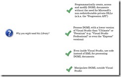
var reasons = new[] {
“Why you might need this Library?”,
“Manipulate DGML outside Visual Studio”,
“Even inside Visual Studio, use code instead of XML for processing DGML documents”,
“Process DGML with a lower version of Visual Studio than “Ultimate” or “Premium” (e.g. “Visual Studio Professional” or even the “Express” versions)”,
“Programmatically create, access and modify DGML documents without the need for Microsoft’s non-redistributable private DLLs (a.k.a. the “Progression API”)”,
};
var g = new DirectedGraph(true) { GraphDirection = “LeftToRight” };
g.Nodes.Add(new Node(reasons[0], “Question”));
g.Nodes.Add(reasons.Skip(1));
var links = from r in reasons.Skip(1)
let q = reasons[0]
select new Link(q, r);
g.Links.Add(links);
g.Styles.Add(new Style(“Node”, “Icon”, Icons.help, “HasCategory(‘Question’)”));
g.Styles.Add(new Style(“Node”, “FontFamily”, “Times New Roman”, “HasCategory(‘Question’)”));
g.Styles.Add(new Style(“Node”, “FontStyle”, “Italic”, “HasCategory(‘Question’)”));
g.Styles.Add(new Style
{
TargetType = “Node”,
Setters =
{
new Setter(“MaxWidth”, “150”),
new Setter(“MinWidth”, “150”),
new Setter(“Shape”, “None”),
new Setter(“FontFamily”, “Century Schoolbook”),
new Setter(“Icon”, Icons.kpi_green_sym2_large),
},
});
g.Styles.Add(new Style(“Link”, “Stroke”, “Transparent”));
var what = new[] {
“What can you do with this library?”,
“Create DGML documents”,
“Modify and annotate DGML documents”,
“Investigate/Manipulate a DGML document without having the proper Visual Studio version or even Visual Studio at all (maybe somebody with “Ultimate” sent it to you)”,
“Use Linq over DGML”,
“Write your own DGML tool with no dependencies on Visual Studio or its DLLs”,
“Represent a DGML diagram using another graph visualization tool (such as “GraphViz”) (I have tools for that)”,
“Translate DGML to SVG, maybe for consuming in your HTML (I have tools for that too)”,
};
var g = new DirectedGraph(true) { GraphDirection = “LeftToRight” };
g.Nodes.Add(new Node(what[0], “Question”));
g.Nodes.Add(what.Skip(1));
var links = from r in what.Skip(1)
let q = what[0]
select new Link(q, r);
g.Links.Add(links);
g.Styles.Add(new Style(“Node”, “Icon”, Icons.help, “HasCategory(‘Question’)”));
g.Styles.Add(new Style(“Node”, “FontFamily”, “Times New Roman”, “HasCategory(‘Question’)”));
g.Styles.Add(new Style(“Node”, “FontStyle”, “Italic”, “HasCategory(‘Question’)”));
g.Styles.Add(new Style
{
TargetType = “Node”,
Setters =
{
new Setter(“MaxWidth”, “150”),
new Setter(“MinWidth”, “150”),
new Setter(“Shape”, “None”),
new Setter(“FontFamily”, “Century Schoolbook”),
new Setter(“Icon”, Icons.kpi_green_sym2_large),
},
});
g.Styles.Add(“Link”, “Stroke”, “Transparent”);

Forgetting to create collections before adding graph elements:
g.Nodes = new Nodes();
g.Nodes.Add(new Node { Id=”1″ });
g.Styles = new Styles();
g.Styles.Add(new Style());


![clip_image048[1] clip_image048[1]](https://ceyhunciper.files.wordpress.com/2011/04/clip_image0481_thumb.jpg?w=244&h=244)
![clip_image050[1] clip_image050[1]](https://ceyhunciper.files.wordpress.com/2011/04/clip_image0501_thumb.jpg?w=244&h=109)


